 |
 |
 |
|
 |
 |
 |
 |
 |
 |
 |
 |
 |
 |
 |
 |
|


 Tech Talk - by Abruzzi
 Go | New | Find | Notify | Tools | Reply |
| Drill & Tap Intake for Ron's | Login/Join |
DRR Trophy |
I am getting ready to drill & tap the holes in my new intake for my Ron's setup. My question in how far do you want the injector to protrude in the port. DOes it matter as long as you have the injector indexed properly? | ||
|
| DRR Top Comp |
I like mine to be where the tip(assuming using same type) where the V notch is about .375 to .500 below top of runner. This keeps out of heaviest air flow while allowing it to spray fuel into air flow in a manor to get good mixture. My 2 cent and I maybe over valuing it at that. America home of free. Brought to you by 2nd amendment. | |||
|
| DRR Trophy |
Ok. Thanks for the info. I don't know if makes any difference I figured I would ask. I figured a few people may have some input on the topic | |||
|
| DRR Top Comp |
Take care to make sure they are straight and far enough up the runner to clear the valve cover. Clowns to the left of me, Jokers to the right. Here I am....... | |||
|
| DRR Pro |
If you have a BBC manifold the nozzle body distance placement from the intake to head mating surface placement is not an issue. Rons instructions says 1” to 1.5”. If this is SBC I suggest not placing the nozzle body any closer than 1.250” if the intake runner exterior protrudes to the outer edges of the manifold mating surface. This is because the angle of the valve cover is much closer to the intake manifold on a SBC and can interfere with the valve cover removal if located to close to the intake mating surface. I just did my SBC intake last weekend that is going to my engine builder on Monday. This intake is ported and does Not have those casting buttons on the outside of the manifold to provide extra surface material to hold the injector nozzle body in place when drilled and tapped. These intake runner exteriors protrude to the outer mating surface edges. These are Rons nozzle bodies in the pic. In Killer Rons installation INSTRUCTIONS it recommends using WD40 to tap with. DO NOT use this fluid. Use a tapping fluid like “Rapid Tap”. Follow the three drill method for the hole. I did NOT use the “R” drill for the final hole size. I use 21/64 drill that is .010 smaller and is listed on the tap I used. I did mine by hand and clamped the intake mating surface at horizontal and drilled holes following this straight down parallel position 1.375” up from the mating surface. I did not use a cable ty to mark the tap depth position as recommended in Rons instructions but instead counted tap turns.  | |||
|
| DRR Elite |
Of course watch the issue with valve cover clearance. But really, I have just shot for the middle of the port and called it good. You don't want it shooting into a wall, but you do want it following the airflow. The physics of the manifold will dictate much of where you can be. I wouldn't go to great lengths to get the perfect location...if there is one. Foxtrot Juliet Bravo | |||
|
| DRR Trophy |
Good write up. Thanks for the time & info
| |||
|
| DRR Trophy |
Thanks for the info. It for sure helps me
| |||
|
| DRR Trophy |
from the look of that pic, you lost count.  6.41@221 (so far) 4.11@178 off the shelf/built it myself | |||
|
| DRR Pro |
You would think this looking at the intakes. This is not the case. The nozzle bodies for the inner ports sit higher on the outside of the manifold than the outer ports. Placing a straight edge level across the 4 bodies together shows this and that they are uniform in depth from the outside surface. The outside surface of the intake is not symmetrical where the nozzle bodies are installed. My guess is that there could possibly be slightly less material on the four inner ports at that area. All were tapped 13.5 turns from the outer surface.  | |||
|
| DRR Sportsman |
MarkeMark is correct. Yup, castings are a B**** I tap our systems on a machine. Because of casting aggravations I machine a flat first for two reasons. 1: It eliminates the frustration of trying to drill on a curved and/or slanted surface. It also comes in handy when I need to tilt the nozzle relative to the manifold surface. Watch how a nozzle flows. It will show you why this is necessary in some cases. 2: It allows equal depth/height of the nozzle bodies when done parallel and equidistant to the manifold centerline. Spot facing gives one the visual impression that things are askew but they are not. The height/thickness of the outside of the castings vary...a lot. As such some of the flats look deeper than others. The above can be done by hand. It just takes a lot more thought, Dykem, measuring, patience and a steady hand. Is all the above necessary? Likely not. It is more of a pro and pride thing than anything else. Most of the time it is a question of space and limitations of where to put the nozzle. Throw in some nitrous and it becomes a mini nightmare. Dave Koehler - Koehler Injection - http://www.koehlerinjection.com Fuel Injection - Nitrous Charger - Nitrous Master Software - Balancing 99% of fuel injection problems are electric. | |||
|
| DRR Trophy |
The last intake I did I positioned the nozzles in the center of the head opening. This put the nozzles NOT centered in the intake runner roof but sort of close-ish to center. I'm doing a new engine like this one and I was pondering placing the nozzles very close, possibly "inside" the divider. This would be a milling machine job for sure. The theory would be the nozzle would not be in the air stream except the bulge. Obviously the indexing would be critical. Wouldn't do much good if the opening was obstructed. 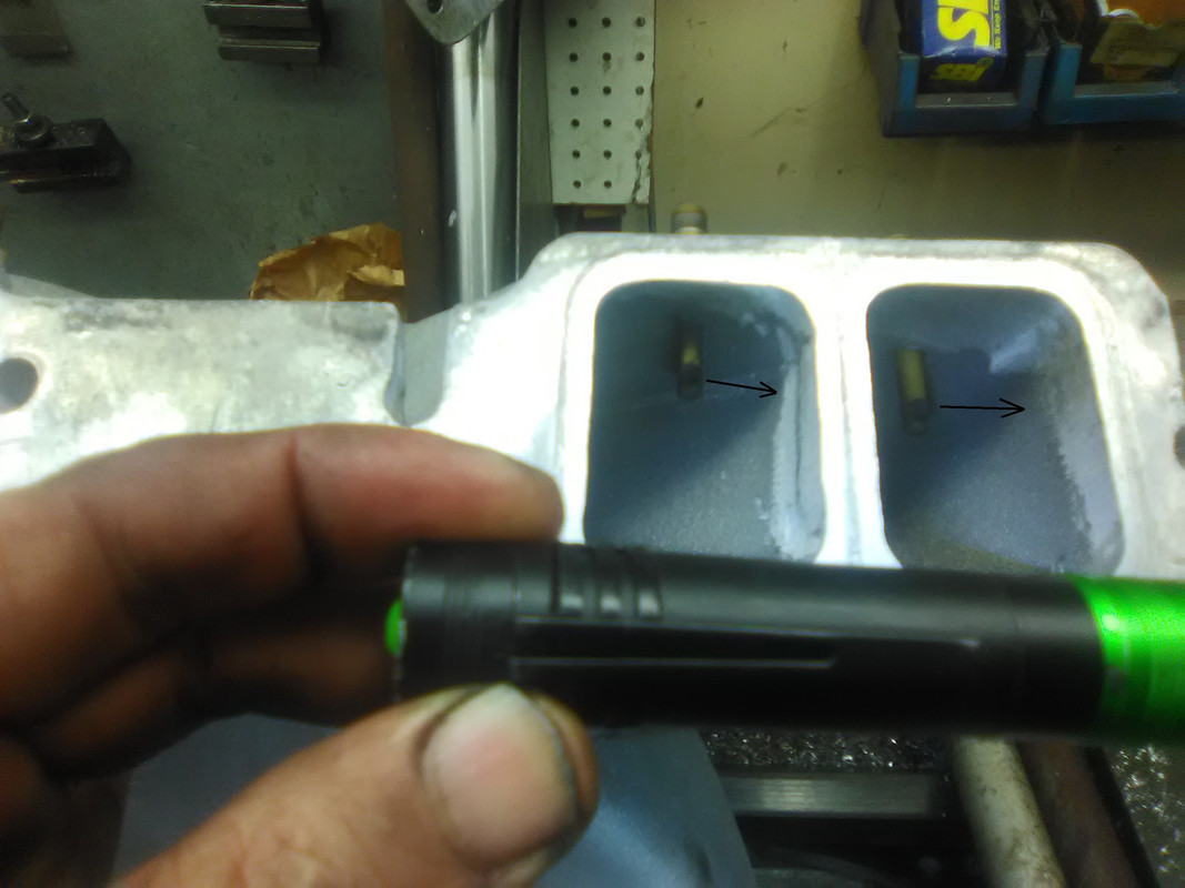 | |||
|
| DRR Sportsman |
I have done a few sets of nitrous nozzles which is a similar process. If you have access to a milling machine it is a lot easier. I bolted one mating surface of the intake to the table and squared the intake to the table. This made it easier to locate the center of the holes. This puts the mating surface of the side you are drilling at 90 degrees to the table. After I drilled without moving the table I changed the drill bit out for a center. I used a tap with a dimple in the top of it and dropped the center into that dimple to align the tap as I turned it. As far as getting the depths the same as said above I counted turns and snuck up on the depth test fitting each time. The same procedure could probably be followed with a drill press accept with no way to move the table horizontally or vertically you would have to reset for each nozzle. I don't know if this is the best or most efficient way but its worked a few times for me. B.J. Masiello | |||
|
| DRR Trophy |
Yep I did have access to a mill machine & that is pretty much the way i did it. Once i drilled the hole I put the tap in and turned it by hand on the top just to get the threads started. Once I got all of them done I finished tapping by hand.
| |||
|
| Powered by Social Strata |
| Please Wait. Your request is being processed... |
Tech Talk - by Abruzzi
 |
 |
 |
 |