 |
 |
 |
|
 |
 |
 |
 |
 |
 |
 |
 |
 |
 |
 |
 |
|


Go | New | Find | Notify | Tools | Reply |
| Grid RPM Shift issues | Login/Join |
| DRR Pro |
You can land both the Yellow and Brown/ White Grid wires together to your shifter input if desired. My car has 4 inputs wired to the shifter. | |||
|
| DRR S/Pro |
The K&R color coded wiring diagram shows the grid connections as terminals and then color coded wires out from those terminals. The terminal labeled brown and white shows a yellow wire going out to the K&R RAS terminal. The terminal labeled yellow on the grid has no wire out. That drawing is available on K&R’s website. I disconnected the brown and white from the grid. Connected the yellow to the RAS terminal on the K&R board. I also disabled the time switch. I enabled the shift light output and set it to what I would usually shift at....7200 I don’t need the time shift feature the grid has. Delay box runs that for me. As always thanks for your posts on the grid. | |||
|
| DRR Top Comp |
It's an odd class if you consider the slow 6.50 index run on a 370 Pro Tree. Heavy slow cars won't do well on a 370 Pro Tree for obvious reasons, imagine running 10.90 NHRA Super Street on a 370 Pro Tree. They don't allow any timers or delay boxes in order to accomplish the shift for this class. But realistically it's a super easy class because the race is pretty much decided on the starting line because if you have a car that'll go that slow (6.50) and the capability to have a good light on a .370 pro tree, you have a distinct advantage. But it's somewhat difficult to have that car. They don't want me in the class now anyway, after making it look way too easy out of the box, which it is a easy class for the reasons I mentioned, but I was just curious what the cure is for shift consistency, on time not rpm, using the Grid.This message has been edited. Last edited by: Mike Rietow, | |||
|
DRR Pro |
Most cars that I wire with a grid I use the shift light (yellow wire) to shift on rpm and the output (brown w/white tracer) to shift on time. With Digital Delay Elite switch panel relay board it really makes it simple using a toggle switch wired to the “select” post to select the shift mode. I wire the K & R kit with a toggle switch also but a little different wiring. I agree with Markemark on using the shift light function to shift at rpm, but make sure you turn the “Power-on Test” off or it will fire the shifter every time you power the car up. Markemark has taught me a lot with the grid ignition and I appreciate his constant support. WiredTwoWin race car wiring | |||
|
| DRR Pro |
I did some searching tonight and found the K&R wiring diagram for Grid that you wrote of HERE . I had to enlarge it on my computer and put my bifocals on to make out the wire landing labels. You are correct. They show a Yellow wire attached to the Grid Brown/ White going to the RAS terminal on the relay board. | |||
|
| DRR Pro |
Yes, I assume a SPDT switch would be a good choice if wanting to be able to quickly select the desired shift mode (RPM or Time). | |||
|
| DRR Pro |
[/QUOTE] I did some searching tonight and found the K&R wiring diagram for Grid that you wrote of HERE . I had to enlarge it on my computer and put my bifocals on to make out the wire landing labels. You are correct. They show a Yellow wire attached to the Grid Brown/ White going to the RAS terminal on the relay board.[/QUOTE] I’m thinking that’s a typo maybe? A drawing error WiredTwoWin race car wiring | |||
|
| DRR Pro |
I did some searching tonight and found the K&R wiring diagram for Grid that you wrote of HERE . I had to enlarge it on my computer and put my bifocals on to make out the wire landing labels. You are correct. They show a Yellow wire attached to the Grid Brown/ White going to the RAS terminal on the relay board.[/QUOTE] I’m thinking that’s a typo maybe? A drawing error[/QUOTE] I agree both are possible. Either way it is Not correct imo. | |||
|
| DRR S/Pro |
I printed out that K&R diagram and also the one to connect the Grid controller to a 7AL3 that I was using before. Had that for over 5 years but used chips for rev limits. I also have the big laminated K&R wiring diagram and that’s very good. What you saw is what I saw and since the brown and white is called out as an rpm switch I just used it as such. Quite a bit of confusion there and I bet it causes a lot of head scratching at the track. MSD could do a better job of explaining that switch output function. Was not real clear to me. Thanks for your help it’s very helpful! | |||
|
| DRR Pro |
Yep, yellow wire to an end post and the brown/white to the other and the center to a relay #85 to fire the shifter. I don’t even use the relay board for shifting when wiring a grid with K&R panel. WiredTwoWin race car wiring | |||
|
| DRR Sportsman |
My K&R relay panel was a switch on it that allows me to shift on RPM (yellow wire) or time (Brown and white).  Are the new ones different? 72 Nova "Hooptie" | |||
|
| DRR S/Pro |
I have the same panel and that's the older version... I replaced my switch panel last summer and Kevin had to find or make an older version to match mine.... I love my K&R stuff, especially my delay box.... It's mounted dead center in my dash and I can and sometimes do make changes just backing up from a burnout....... | |||
|
| DRR Trophy |
The new K&R has a 4 legged jumper that needs to be swapped to switch from time to RPM. I would like to find a simple way to switch it myself. I do like that toggle. The Digital delay board has a slide switch on it. Dale Below you can see the wires to swap on the newer K&R. 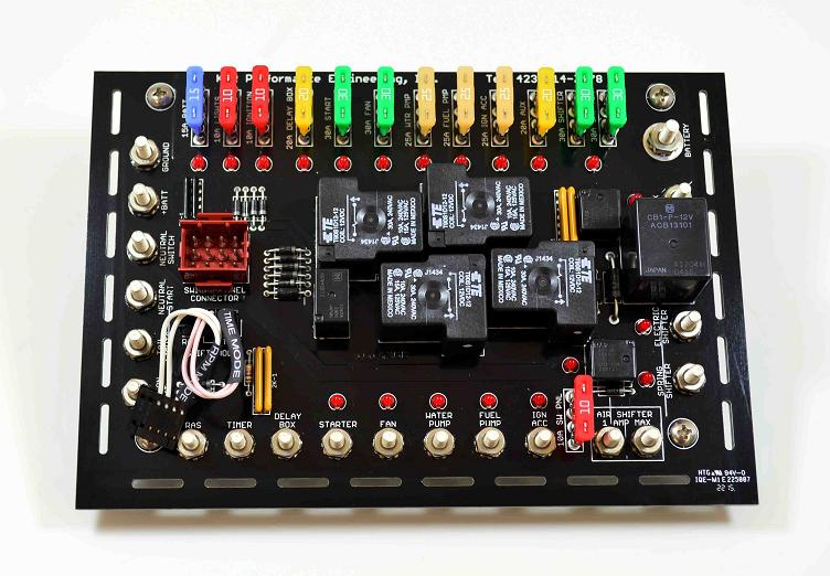 | |||
|
| DRR Pro |
Use a SPDT toggle switch and land the center leg to the relay board. The RPM lands on one side of the switch and the Timer lands on the other side. LIKE THIS | |||
|
| DRR Trophy |
I understand the switch, what is the part to order the connector to the board? Nice picture of it with the white wires and says RPM MODE? | |||
|
| DRR Pro |
? Not sure what you’re asking WiredTwoWin race car wiring | |||
|
| DRR Sportsman |
You’d wire around that. One side of the SPDT switch gets the wire that’s currently on the RPM shift terminal. The other side gets the wire there currently on the timer shift terminal. The middle of the switch goes to either the timer or rpm switch terminal of the wiring board and you set the wire jumper to whichever terminal you hooked the middle wire to. I hope that makes sense. | |||
|
| DRR Trophy |
Gotcha thanks, I was thinking of using the K&R connector but obviously taking it out of the picture would work with a switch also. Dale | |||
|
| Powered by Social Strata | Page 1 2 |
| Please Wait. Your request is being processed... |
 |
 |
 |
 |
